COLD CHAMBER / MT1600
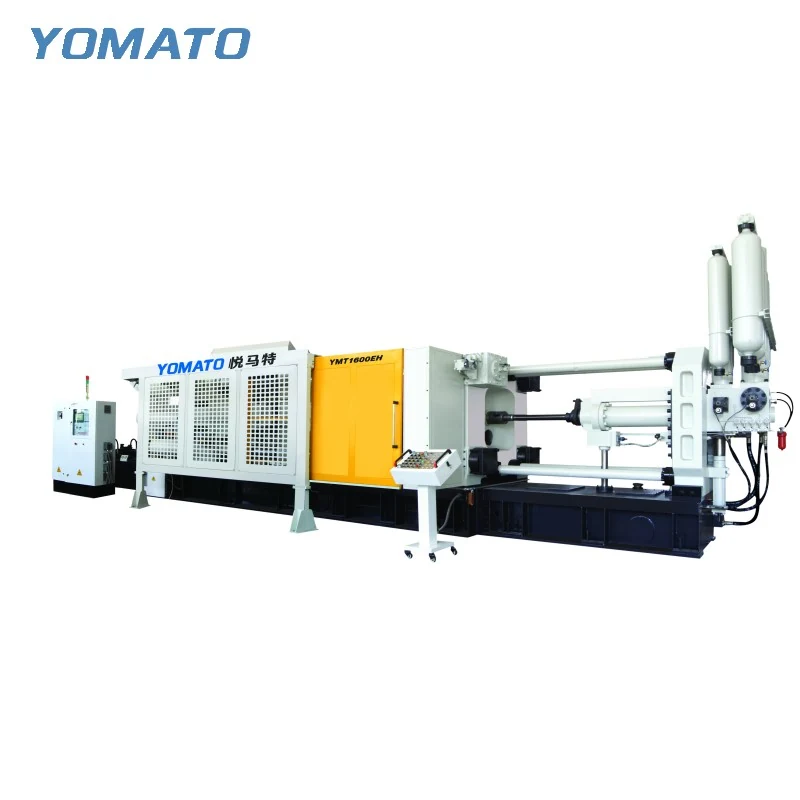
MT1600 Die Casting Machine
The MT1600 cold chamber machine should be assessed through the tooling it will carry and the full casting system it will inject. For aluminum, magnesium and copper alloy projects, begin with the closed die stack, then study opening, release and the production area around the machine.
Request an MT1600 Quote ↗MT1600 technical specifications
| Parameter | Unit | MT1600 |
|---|---|---|
| Clamping Force | KN | 16000 |
| Platen Size (HxV) | mm | 1900x1900 |
| Space Between Tie Bars (HxV) | mm | 1200x1200 |
| Tie Bar Diameter | mm | 250 |
| Mold Height (Min.-Max.) | mm | 600-1300 |
| Clamping Stroke | mm | 1100 |
| Ejection Stroke | mm | 220 |
| Ejection Force | KN | 650 |
| Injection Force | KN | 1300 |
| Injection Stroke | mm | 1000 |
| Injection Position | mm | 0,-350 |
| Injection Plunger Diameter | mm | 110-150 |
| Injection Weight (Al) | KG | 18-36 |
| Casting Pressure (Intensify.) | MPa | 140-71 |
| Casting Area | cm2 | 1100-2200 |
| Max. Casting Area (40MPa) | cm2 | 4000 |
| Casting Flange Protrusion | mm | 25-0.05 |
| Casting Flange Diameter | mm | 260 |
| Plunger Penetration | mm | 400 |
| System Working Pressure | MPa | 16 |
| Motor Power | KW | 90 |
| Oil Tank Capacity | L | 2600 |
| Machine Weight | KG | 110000 |
| Machine Dimensions (LxWxH) | m | 13.5x3.8x4.2 |
01 / SERIES
Review the complete tooling depth
The MT1600 mould height range is 600-1300 mm. Establish the closed dimension from the actual mounting faces, including any plates and adapters that remain during operation. The 1900x1900 mm platen and 1200x1200 mm tie bar spacing describe the other principal tooling boundaries. Show both on the assembly drawing, along with the loading direction. A sizeable cavity block may be only part of the installed envelope once slides, manifolds and lifting features are included. Identify items connected after insertion and their final operating positions. Tool changes need access to fixing points as well as clearance for the incoming assembly. A review based on those practical details can reveal requirements that would be missed by comparing the finished casting with the nominal machine designation.
02 / SERIES
Describe an injection configuration for the whole shot
MT1600 lists a 110-150 mm plunger diameter range and an 18-36 KG aluminum injection weight range. The full shot includes metal that does not remain in the final component, so provide the runner and other feed system estimate with the part mass. State the alloy designation and any planned cavity arrangement. The aluminum weight reference should remain attached to its specified material. Injection force is 1300 KN and injection stroke is 1000 mm. Use these fields together when discussing a proposed plunger and mould configuration. Show the gate concept and the features that make filling significant, including ribs, thick junctions and distant portions of the cavity. Where tooling remains preliminary, explain the assumptions behind the metal estimate rather than treating them as fixed production values.
03 / SERIES
Plan extraction around the released assembly
MT1600 clamping stroke is 1100 mm, with a 220 mm ejection stroke. These values need an accompanying movement study that shows the casting at opening, at release and during withdrawal. Include its feed system if it remains attached while the extractor holds the part. Gripping hardware must clear the tool as well as carry the casting, so its envelope belongs in the review. Cooling connections and side actions should be shown in their operating positions. Spraying adds another motion through the open area and may require a different direction of approach. Explain how those tasks are sequenced and where devices wait while the machine cycles. If a retained extractor or sprayer is proposed, attach its reach and mounting information to the tooling brief.
04 / SERIES
Make installation planning part of selection
The MT1600 machine measures 13.5x3.8x4.2 m and has a listed weight of 110000 KG. Bring this information into the site and installation review before finalizing equipment placement. The production layout also includes furnace access, metal transfer, discharge handling and room for service. Mark building access, fixed structures and the intended operating positions on a dimensioned plan. The motor power is 90 KW, with the requirements of separately selected auxiliaries to be considered in addition. Temperature control lines should have practical routes to the tool, and castings need a defined destination after extraction. An MT1600 enquiry is most useful with the component drawing, alloy, complete mould dimensions and shot requirement. Identify existing equipment and site restrictions so the discussion can address a coordinated installation. Separate the normal operator route from the access used during tool changes. Both need to be understood on the plan, because a production arrangement that appears open during cycling may become constrained when lifting and tool servicing activities are included.
PROJECT ENQUIRY
Discuss your
casting project
Send your alloy, part drawing details, mould dimensions and project location. Confirm order quantity and delivery requirements with your quotation request.
Prefer email?
[email protected]