COLD CHAMBER / MT2000
MT2000 Die Casting Machine
MT2000 enquiries should describe a complete production task: the alloy, the tool, the metal requirement and the casting discharge route. This MT cold chamber model covers aluminum, magnesium and copper alloy projects. Review its injection and tooling dimensions directly, then connect those checks to the available installation area.
Request an MT2000 Quote ↗MT2000 technical specifications
| Parameter | Unit | MT2000 |
|---|---|---|
| Clamping Force | KN | 20000 |
| Platen Size (HxV) | mm | 2100x2100 |
| Space Between Tie Bars (HxV) | mm | 1300x1300 |
| Tie Bar Diameter | mm | 280 |
| Mold Height (Min.-Max.) | mm | 650-1400 |
| Clamping Stroke | mm | 1200 |
| Ejection Stroke | mm | 240 |
| Ejection Force | KN | 750 |
| Injection Force | KN | 1500 |
| Injection Stroke | mm | 1100 |
| Injection Position | mm | 0,-380 |
| Injection Plunger Diameter | mm | 120-160 |
| Injection Weight (Al) | KG | 22-44 |
| Casting Pressure (Intensify.) | MPa | 140-71 |
| Casting Area | cm2 | 1400-2800 |
| Max. Casting Area (40MPa) | cm2 | 5000 |
| Casting Flange Protrusion | mm | 25-0.05 |
| Casting Flange Diameter | mm | 280 |
| Plunger Penetration | mm | 420 |
| System Working Pressure | MPa | 16 |
| Motor Power | KW | 110 |
| Oil Tank Capacity | L | 3000 |
| Machine Weight | KG | 140000 |
| Machine Dimensions (LxWxH) | m | 14.5x4.0x4.4 |
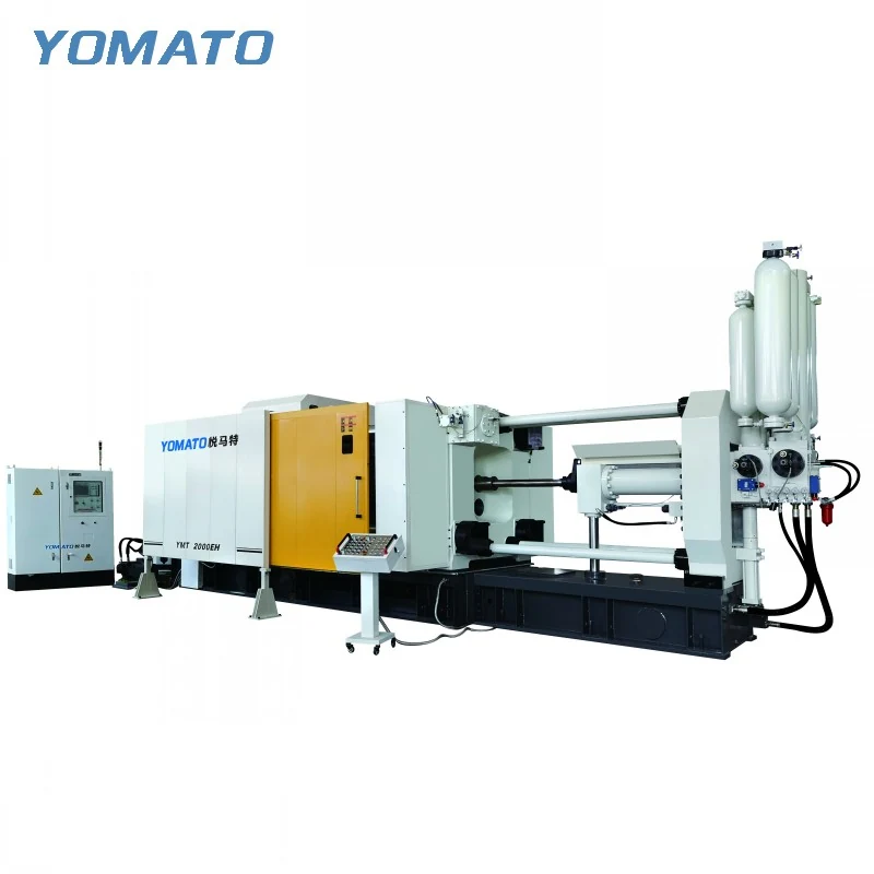
01 / SERIES
Check the die in both loading and working positions
The MT2000 platen is 2100x2100 mm, and tie bar spacing is 1300x1300 mm. Overlay the complete tool assembly on these boundaries, retaining slides, mounting plates and projecting fittings. The route used to load the die may place different constraints on the assembly from its final mounted position. Mark the loading direction and the hardware that can be connected afterward. The mould height range is 650-1400 mm. Compare that window with the full closed stack, measured between mounting faces. Include access to fastenings, ejection interfaces and cooling connections so the machine discussion addresses serviceability as well as nominal fit. Existing tools need an explanation of their current mounting arrangement and any changes proposed for use in the new production cell.
02 / SERIES
Establish the complete mass delivered to the tool
MT2000 aluminum injection weight is listed at 22-44 KG, with a 120-160 mm injection plunger diameter range. Account for the feed system in addition to the component when establishing the shot requirement. The runner, biscuit and overflow concept can influence that requirement substantially. State the actual alloy, keeping the aluminum reference connected to the material named in the specification. Injection force is 1500 KN and injection stroke is 1100 mm. Discuss those fields with the proposed plunger and gating arrangement rather than choosing isolated extremes from the table. Show the cavity layout and highlight geometrical features that complicate filling. If several parts share the proposed machine, provide their tooling and shot briefs separately so the comparison does not hide important differences between production tasks.
03 / SERIES
Define removal before fixing peripheral positions
The MT2000 has a 1200 mm clamping stroke and a 240 mm ejection stroke. Draw the release process with the whole casting assembly and intended gripper present. A runner or projecting feature can affect both the gripping position and the route through the open die. Check clearance to cooling lines, side mechanisms and tooling faces along that route. The die sprayer needs its own approach after extraction, so its movement should appear in the same sequence study. Explain how the casting is placed outside the machine and what operation follows. An extractor, conveyor or trimming arrangement cannot be positioned usefully without that destination. Include retained auxiliary equipment with its reach and connection details so compatibility can be reviewed against the actual proposed tool and handling sequence.
04 / SERIES
Use the installation outline without losing service space
MT2000 dimensions are 14.5x4.0x4.4 m and the listed machine weight is 140000 KG. The site review should consider these values alongside installation access and the surrounding equipment. Mark the furnace, ladling route and discharge zone on the floor plan, then reserve working room for operators and maintenance. Mould temperature controllers and release agent mixers also need accessible connection routes. The machine motor power is 110 KW; selected peripherals add separate utility requirements to the planning exercise. For an MT2000 quotation, provide the drawing revision, alloy, complete die envelope and whole shot estimate. Explain building constraints and identify equipment that will remain in use. A coordinated set of inputs gives the discussion a practical basis for machine configuration and cell layout. If castings are handed directly to another process, define the receiving position and orientation. This lets the handling discussion connect the released casting to a specific downstream task, with its attached runner and other temporary features still accounted for.
PROJECT ENQUIRY
Discuss your
casting project
Send your alloy, part drawing details, mould dimensions and project location. Confirm order quantity and delivery requirements with your quotation request.
Prefer email?
[email protected]