COLD CHAMBER / MT550
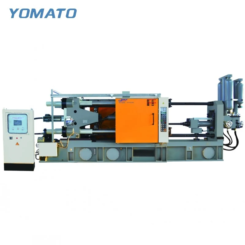
MT550 Die Casting Machine
MT550 cold chamber selection involves more than its clamping designation. For aluminum, magnesium and copper alloy projects, compare the die envelope and complete shot with the machine table, then examine removal access. A coordinated enquiry helps keep tooling, injection and floor layout aligned throughout the discussion.
Request an MT550 Quote ↗MT550 technical specifications
| Parameter | Unit | MT550 |
|---|---|---|
| Clamping Force | KN | 5500 |
| Platen Size (HxV) | mm | 1300x1300 |
| Space Between Tie Bars (HxV) | mm | 850x850 |
| Tie Bar Diameter | mm | 205 |
| Mold Height (Min.-Max.) | mm | 400-1000 |
| Clamping Stroke | mm | 800 |
| Ejection Stroke | mm | 190 |
| Ejection Force | KN | 320 |
| Injection Force | KN | 750 |
| Injection Stroke | mm | 800 |
| Injection Position | mm | 0,-250 |
| Injection Plunger Diameter | mm | 90-120 |
| Injection Weight (Al) | KG | 7.0-14.0 |
| Casting Pressure (Intensify.) | MPa | 125-60.3 |
| Casting Area | cm2 | 440-920 |
| Max. Casting Area (40MPa) | cm2 | 1375 |
| Casting Flange Protrusion | mm | 20-0.05 |
| Casting Flange Diameter | mm | 210 |
| Plunger Penetration | mm | 400 |
| System Working Pressure | MPa | 16 |
| Motor Power | KW | 55 |
| Oil Tank Capacity | L | 1500 |
| Machine Weight | KG | 30000 |
| Machine Dimensions (LxWxH) | m | 10.0x2.7x3.5 |
01 / SERIES
Treat projecting tooling features as real space
An MT550 offers 850x850 mm between tie bars and a 1300x1300 mm platen. Draw the tooling against both boundaries, including slides, manifolds and fittings that project from the main block. The die loading route may have different constraints from the final mounted position. Show which items can be installed after loading and which remain part of the assembly throughout. The mould height window is 400-1000 mm. Include the whole closed stack when comparing this dimension, using the intended mounting faces as references. Tool changes should also have a defined lifting approach and access to fastenings. Describing those details early helps turn a nominal fit comparison into a practical installation discussion, especially when an existing mould will be reused.
02 / SERIES
Define a shot around the mould rather than the part
The MT550 table lists a 90-120 mm injection plunger diameter range and 7.0-14.0 KG aluminum injection weight. Develop the metal requirement for the component and its runner, biscuit and overflow arrangement. The finished part alone gives an incomplete view of what the injection unit must deliver. An aluminum weight field should also remain tied to that material during comparison; identify the actual alloy in the enquiry. Injection force is 750 KN, with an 800 mm injection stroke. Review those specifications as part of a proposed injection arrangement, not as independent promises that apply to every tool. The gating concept, cavity layout and areas with changing section thickness help explain the filling task. Include them even if the tooling design remains preliminary.
03 / SERIES
Use the open position to plan two different tasks
A clamping stroke of 800 mm creates the MT550 opening, and the listed ejection stroke is 190 mm. Removal and die preparation then place different demands on that space. For removal, consider the casting in the orientation in which it leaves the die, with its feed system attached where applicable. Add the gripper and withdrawal movement. For preparation, identify surfaces that need spray access, including those near side actions or recessed tooling features. A device that can reach the main cavity may still require a separate review around projections. Explain the intended task order and any peripheral equipment to be retained. This allows the machine enquiry to address access and timing relationships instead of presenting the auxiliaries as isolated purchases.
04 / SERIES
Give the production area a material flow
MT550 dimensions are 10.0x2.7x3.5 m, and the machine weight is 30000 KG. Bring the installation outline into the building plan, then add operating and service areas. The furnace and ladler establish the incoming metal route; extraction and conveying establish the outgoing casting route. A trimming operation may extend that route beyond the immediate machine area. Locate temperature control and release agent supply with their connections in mind, keeping them understandable to operators and maintenance staff. Provide the alloy, casting drawing, mould envelope and full shot estimate when requesting an MT550 quote. If space is constrained, attach a dimensioned floor layout and identify fixed obstacles. Clarify the downstream operation and existing auxiliaries so the proposed cell can be discussed as a working arrangement. If the casting moves directly toward a trimming station, show the orientation required at that station. The extractor discharge arrangement and any conveyor handover can then be discussed around a defined next step, rather than an unspecified collection area beside the machine.
PROJECT ENQUIRY
Discuss your
casting project
Send your alloy, part drawing details, mould dimensions and project location. Confirm order quantity and delivery requirements with your quotation request.
Prefer email?
[email protected]