COLD CHAMBER / MT400
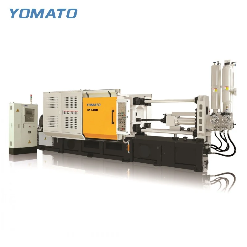
MT400 Die Casting Machine
MT400 die casting machine for aluminum, magnesium and copper alloys. Compare the clamping space and injection unit with your mould before planning the surrounding cell.
Request an MT400 Quote ↗MT400 technical specifications
| Parameter | Unit | MT400 |
|---|---|---|
| Clamping Force | KN | 4000 |
| Platen Size (HxV) | mm | 1080x1080 |
| Space Between Tie Bars (HxV) | mm | 700x700 |
| Tie Bar Diameter | mm | 175 |
| Mold Height (Min.-Max.) | mm | 350-850 |
| Clamping Stroke | mm | 650 |
| Ejection Stroke | mm | 160 |
| Ejection Force | KN | 260 |
| Injection Force | KN | 600 |
| Injection Stroke | mm | 650 |
| Injection Position | mm | 0,-220 |
| Injection Plunger Diameter | mm | 70-100 |
| Injection Weight (Al) | KG | 4.5-9.0 |
| Casting Pressure (Intensify.) | MPa | 125-60.3 |
| Casting Area | cm2 | 320-660 |
| Max. Casting Area (40MPa) | cm2 | 1000 |
| Casting Flange Protrusion | mm | 20-0.05 |
| Casting Flange Diameter | mm | 180 |
| Plunger Penetration | mm | 340 |
| System Working Pressure | MPa | 16 |
| Motor Power | KW | 37 |
| Oil Tank Capacity | L | 1200 |
| Machine Weight | KG | 20000 |
| Machine Dimensions (LxWxH) | m | 8.5x2.4x3.2 |
TOOLING / SHOT / CELL
A machine selection starts with the part.
Bring the drawing, alloy and mould envelope into the same discussion. Work through the MT400 clamping space, injection unit and handling requirements below.
Request an MT400 Quote ↗01 / DETAIL
Read the MT400 around your mould
The MT400 brings a 700x700 mm tie bar space and 1080x1080 mm platen size into the tooling discussion. Start with the full die envelope, including anything projecting beyond the mould plates. The mounting face, tie bar opening and service connections need to be considered together. A drawing of the complete assembly is more useful than the dimensions of the cavity alone.
The mould height range is 350-850 mm, while clamping stroke is 650 mm. Check both against the tool in its installed and open positions. Include the clearance needed for the casting, runner system and any removal equipment. The 160 mm ejection stroke is another separate check: the tool and its ejection arrangement must be discussed alongside the movement needed to release the component.
Do not select the press from casting weight alone. The MT400 table lists 4000 KN clamping force, but tool size, projected casting area and the injection task remain distinct selection inputs. Bring the mould drawing and part geometry to the enquiry so the conversation can address those inputs together.
02 / DETAIL
Match the shot to the component
The MT400 injection unit lists 600 KN injection force, a 650 mm injection stroke and a 70-100 mm plunger diameter range. Its aluminum injection weight range is 4.5-9.0 KG. Use these fields as a connected set when discussing your casting. The metal requirement includes the feed system as well as the finished part, so a component weight by itself cannot describe the whole shot.
Share the alloy designation and drawing revision with the required casting geometry. Identify thin sections, deep features and any finishing requirements that affect how the die and injection process should be considered. Ask for a configuration discussion around the proposed mould and plunger combination rather than choosing each field independently.
The table also separates casting area from maximum casting area at the stated pressure. Keep that distinction when comparing options. Review the entire parameter set with the tooling requirement, and include the gating and ejection arrangement in the technical discussion. A short list built around those checks is more useful than a comparison based only on nominal machine size.
03 / DETAIL
Define the part before the application label
MT cold chamber machines serve automotive parts, motorcycle accessories, home appliances, electronic products, hardware accessories and machinery accessories. For an MT400 enquiry, describe the component within that field: its alloy, complete geometry, mould dimensions and handling task. The application name helps explain the context, while the drawings provide the detail needed to discuss the equipment.
Include the operations after ejection. Explain whether the casting needs conveying, cooling or trimming, and identify where those tasks will take place. This gives the machine and auxiliary equipment discussion a shared starting point without assuming that every part in an industry uses the same tooling or cell layout.
04 / DETAIL
Build an MT400 cell around access
YOMATO auxiliary equipment includes an auto ladler for metal transfer, an auto sprayer for the die and an auto extractor for part removal. Melting and holding furnaces, conveyor belts, mould temperature controllers, release agent mixers and hydraulic trimming presses extend the equipment discussion beyond the machine. Select the combination around the casting task and the intended layout.
For the MT400, map the approach to the shot sleeve, access to both die faces and the route out of the open tool. Include the furnace location and the space needed to service the equipment. Describe any existing auxiliaries you intend to reuse, including their connection requirements and handling envelope.
Prepare a quotation enquiry with the part drawing, alloy, mould envelope, shot requirement, utility information and project location. Add a floor plan where available. Confirm order quantity and delivery requirements with the enquiry. Browse the cold chamber family if you are comparing machine sizes, or read the process guide to review how clamping, injection and ejection fit together.
PROJECT ENQUIRY
Discuss your
casting project
Send your alloy, part drawing details, mould dimensions and project location. Confirm order quantity and delivery requirements with your quotation request.
Prefer email?
[email protected]