COLD CHAMBER / MT700
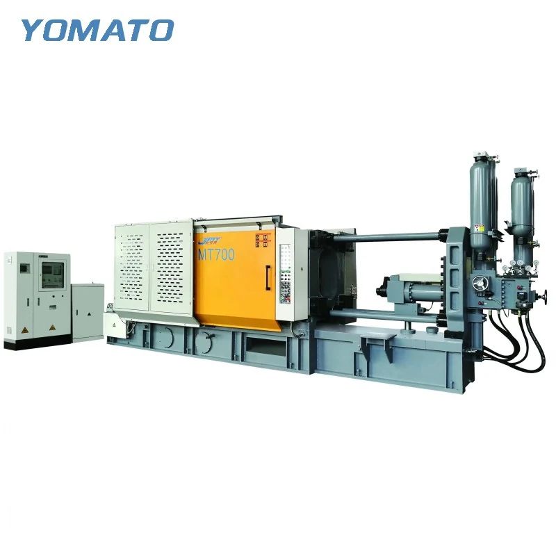
MT700 Die Casting Machine
The MT700 has its own tooling and injection specification within the MT cold chamber family. Evaluate it directly for your aluminum, magnesium or copper alloy project. In particular, its listed plunger options and associated injection fields deserve a connected review alongside the mould assembly and installation layout.
Request an MT700 Quote ↗MT700 technical specifications
| Parameter | Unit | MT700 |
|---|---|---|
| Clamping Force | KN | 7000 |
| Platen Size (HxV) | mm | 1260x1250 |
| Space Between Tie Bars (HxV) | mm | 820x820 |
| Tie Bar Diameter | mm | 165 |
| Mold Height (Min.-Max.) | mm | 350-900 |
| Clamping Stroke | mm | 650 |
| Ejection Stroke | mm | 160 |
| Ejection Force | KN | 260 |
| Injection Force | KN | 620 |
| Injection Stroke | mm | 650 |
| Injection Position | mm | 0,-250 |
| Injection Plunger Diameter | mm | 80,90,110 |
| Injection Weight (Al) | KG | 6.1,7.8,9.6 |
| Casting Pressure (Intensify.) | MPa | 123,97,79 |
| Casting Area | cm2 | 567,718,886 |
| Max. Casting Area (40MPa) | cm2 | 1750 |
| Casting Flange Protrusion | mm | 15-0.05 |
| Casting Flange Diameter | mm | 165 |
| Plunger Penetration | mm | 280 |
| System Working Pressure | MPa | 16 |
| Motor Power | KW | 37 |
| Oil Tank Capacity | L | 1200 |
| Machine Weight | KG | 30000 |
| Machine Dimensions (LxWxH) | m | 8.2x2.5x3.3 |
01 / SERIES
Begin with the MT700 tooling dimensions
MT700 tie bar spacing is 820x820 mm, while the platen measures 1260x1250 mm. Preserve the distinct horizontal and vertical platen dimensions when laying out the tool interface. A general description such as a square mounting area would lose useful information. The mould height range is 350-900 mm. Compare the closed tool, including its installed plates and adapters, with that window. Side actions and cooling fittings should appear in both their operating positions and the proposed loading arrangement. Show the lifting direction and any projections that must clear the tie bars. These checks establish how the assembly reaches its working position and how its connections remain accessible, rather than merely demonstrating that a cavity block fits within the nominal opening.
02 / SERIES
Read the plunger choices without blending configurations
The MT700 lists injection plunger diameters of 80,90,110 mm. Its aluminum injection weights are 6.1,7.8,9.6 KG, with casting pressure values of 123,97,79 MPa. Keep those listed fields visible together when discussing the intended injection arrangement. Do not combine whichever individual value appears largest into an assumed configuration. Supply the complete metal requirement for the mould, including the feed system, and explain the selected alloy. The runner concept and cavity geometry help determine the questions that need answering around plunger selection. Thin sections, longer filling paths and important surface features should be marked on the casting drawing. A clear shot brief is more useful than choosing MT700 solely because a finished part appears to fall below a listed weight.
03 / SERIES
Check release travel against the handling approach
The MT700 clamping stroke is 650 mm and its ejection stroke is 160 mm. Establish where the casting is positioned after ejection before arranging an extractor. The runner and any projecting features must be included in the accessible envelope, together with the gripper. Review the path out of the tool for interference with slides, connections and peripheral equipment. Die spraying is a separate task in the same region, so map the approach to the die faces as well as the part removal route. Explain whether the cell uses existing equipment and provide its mounting and reach information. A layout with these movements drawn can make potential conflicts visible during the enquiry, while machine and auxiliary configurations are still being considered.
04 / SERIES
Fit the surrounding equipment to the actual outline
The MT700 machine dimensions are 8.2x2.5x3.3 m, with a listed weight of 30000 KG. Use those specific values for the site discussion rather than estimating an outline from the model name. A complete cell also needs furnace space, metal transfer access, a discharge area and service routes. The motor power is listed at 37 KW; selected auxiliaries add their own utility requirements to the installation plan. Place the furnace relative to the shot sleeve and show where a casting goes after extraction. If a conveyor or trimming press is included, map that next operation too. Request an MT700 quotation with the alloy, mould assembly, complete shot estimate and floor layout. Identify retained equipment so its interfaces can be assessed alongside the proposed machine. Include the specific die revision associated with the shot estimate. If gating changes during design, update the metal requirement alongside the geometry so the proposed plunger discussion continues to reflect the same tool and component rather than mismatched stages of development.
PROJECT ENQUIRY
Discuss your
casting project
Send your alloy, part drawing details, mould dimensions and project location. Confirm order quantity and delivery requirements with your quotation request.
Prefer email?
[email protected]